The first major project for this class was an exercise in metrology, the study of measurements. The motivation for this project stems from the idea that in many circumstances, an engineer will have to make a part that interfaces with another. However, the engineer may not have access to the means of making a prototype. Rather the engineer will have to make a part drawing and have it sent off to a manufacturer to have hundreds of products produced. A mistake in the drawing can be very expensive and wasteful, hence the following mantra stands: "Measure twice, cut once". In other words, measurements must be made accurately and detailed on a drawing clearly such that a manufacturer can produce the desired part as intended and that the part will be able to interface as expected.
|
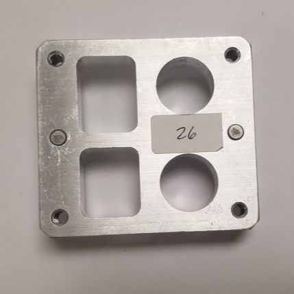
Project goals: The major goal of this project is to design and manufacture a gasket to be fitted over an aluminum block with a deadline of just one week from the assignment. This block has a collection of features on it that had to be accounted for, as well as a set of pins on which the gasket would be mounted on. The gasket was evaluated based on how well they fit on the block, i.e. if everything was within tolerance. The block I was assigned is shown on the left.
Learning Objectives: Throughout the process of completing this assignment, I was introduced to the basic skills needed to manufacture mechanical components in the EPIC workshop. These skills include:
|
Getting the Block
In the beginning, I was given my assigned block, a caliper set, a blank piece of paper, and a pencil. From here, I had 105 minutes to make an accurate sketch of the block before me. After that time was up, I would not see that block again until I tested my gasket to see if it fit properly. I started by making a rough sketch of the block, noting all of the features of the block as well as the overall shape. Then I got to work making measurements. Using my caliper set, I measured everything I needed in order to make an accurate CAD model on Solidworks. This included the outside dimensions, the dimensions of the internal features, and the locations of the internal features with respect to the edges of the part. Everything was measured twice to ensure accuracy. Below is the resulting sketch:
In the beginning, I was given my assigned block, a caliper set, a blank piece of paper, and a pencil. From here, I had 105 minutes to make an accurate sketch of the block before me. After that time was up, I would not see that block again until I tested my gasket to see if it fit properly. I started by making a rough sketch of the block, noting all of the features of the block as well as the overall shape. Then I got to work making measurements. Using my caliper set, I measured everything I needed in order to make an accurate CAD model on Solidworks. This included the outside dimensions, the dimensions of the internal features, and the locations of the internal features with respect to the edges of the part. Everything was measured twice to ensure accuracy. Below is the resulting sketch:
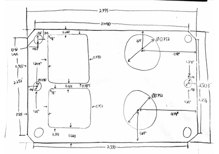
The sketch of the aluminum block I was assigned, fully dimensioned.
|
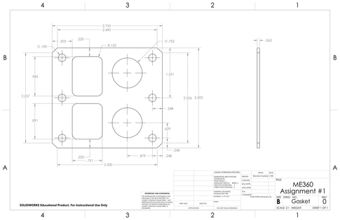
The CAD drawing of the gasket from my sketch.
|
Designing and Machining
With the sketch I made, I got to work on creating a CAD model. As stated before, this was all done in Solidworks. Once I had the CAD model, I ported it into GibbsCAM. This computer aided manufacturing software, when set up correctly, will generate G Code, instructions a CNC mill will follow in order to machine a part from raw material. The material I used was a 1/16" thick PVC square. After all of this, the resulting product was a gasket ready to be tested. Below are some pictures of the CAD model and final product, as well as a short video of the part being machined.
With the sketch I made, I got to work on creating a CAD model. As stated before, this was all done in Solidworks. Once I had the CAD model, I ported it into GibbsCAM. This computer aided manufacturing software, when set up correctly, will generate G Code, instructions a CNC mill will follow in order to machine a part from raw material. The material I used was a 1/16" thick PVC square. After all of this, the resulting product was a gasket ready to be tested. Below are some pictures of the CAD model and final product, as well as a short video of the part being machined.
|
|
|
Evaluation
My gasket fit perfectly! All of the measurements I had made were accurate and well toleranced; the gasket was able to freely slide on and off of the pins of the block and all of the features were aligned.
My gasket fit perfectly! All of the measurements I had made were accurate and well toleranced; the gasket was able to freely slide on and off of the pins of the block and all of the features were aligned.
