A huge part of being a mechanical engineer is understanding how mechanisms work together. There used to be entire classes on this topic, however this has changed. In a previous project, I analyzed a 4bar mechanism that was made and simulated on Solidworks. The next step after that was building a physical mechanism, and what better way to do that than via a motion system. Motion systems are very important because understanding how they work allows for effective application in any project that requires some sort of movement, as does this project. The last and final project for this class would be my biggest and most ambitious to date, and it will require using all of my knowledge I have gained in previous classes as well as applying my newfound knowledge gained via this class.
Update: This project was ranked number 1 out of all the projects in my class!
Update: This project was ranked number 1 out of all the projects in my class!
|
Project Goals: Linear motion systems are very useful mechanisms used almost everywhere in automated systems. However, there is no one component that can achieve this motion unlike with rotational motion where a lone motor can achieve this. Rather, in order to create a linear motion, rotational motion must be converted. Because of their usefulness, understanding how to build a linear motion system is imperative to creating motion systems in general. To achieve this goal, a 2.5 axis motion system was to be made that allows linear drives to work together in order to accomplish some task.
Learning Goals: Completion of this project utilized many of the skills learned both in the classroom as well as in previous classes:
|
|
The Idea
The idea that my group settled on was one similar to that of a CNC plotter. This arose because myself and another group member conduct research in the BU Robotics Lab where we focus on image recognition and environment awareness. The goal was to create a device that could take a picture of a person, trace out the person's face, and draw it. The face detection and tracing would take place on a laptop computer which would convert the traces image to gcode, a code that CNC machines use to operate. Through a Java program, the gcode would be streamed to an Arduino Uno board that would interpret the code and move the components of the machine accordingly. The end result would be a robotically drawn image using a pen on paper. As time went on, this idea evolved to the point where any image could be inputted into the device rather than solely faces. |
|
Mechanism Design
With the idea set, the next major step was determining how to achieve this design. The mechanism part was focused on first. Admittedly, I was not as involved in this stage of the design process as I focused more of my efforts towards the circuitry and software components. More on that later. My group decided to go with a movement system based on the mechanism present in the popular toy, the Etch-a-Sketch. Originally, the idea was to have the two movement axes intermingled in a way that allowed the plotter to move the pen in both the x and y directions. However, after a brief redesign and meeting with our Professor, we decided that a more simple design would entail that the the two axes were separated from each other; the pen would only move in one direction (in our case we defined it as the y-direction) and the work-bed would move in the other direction (the x direction). These two axes constituted 2 of the 2.5 movement systems
With the idea set, the next major step was determining how to achieve this design. The mechanism part was focused on first. Admittedly, I was not as involved in this stage of the design process as I focused more of my efforts towards the circuitry and software components. More on that later. My group decided to go with a movement system based on the mechanism present in the popular toy, the Etch-a-Sketch. Originally, the idea was to have the two movement axes intermingled in a way that allowed the plotter to move the pen in both the x and y directions. However, after a brief redesign and meeting with our Professor, we decided that a more simple design would entail that the the two axes were separated from each other; the pen would only move in one direction (in our case we defined it as the y-direction) and the work-bed would move in the other direction (the x direction). These two axes constituted 2 of the 2.5 movement systems
|
|
|
The last part was figuring out how to achieve the .5 movement system. To clarify, a full movement axis entails that the linear drive can move to any point between its two extremes. A half movement axis means that the linear drive can only move to its to extremes and no other point. If we think of these extremes as 0 and 1, the full axis can move to any fraction between and including 0 and 1 whereas the half can only move to 0 or 1. For our plotter, the .5 axis would be the z-axis because the pen only needs two states, up such that id does not contact the paper, and down such that it does in order to draw. To achieve this, we decided on using a solenoid. When electricity is applied to the solenoid, the plunger of the solenoid would push the pen into the paper with a bit of pressure, thus allowing it to draw.
|
|
Originally, up until the final iteration of the prototype, the pen was held from the very top, the furthest point from the writing end. After a bout of testing however, we realized that this was not a good idea, if held from this position, the pen has a very high torque as it draws which causes the y-axis to jam.
|
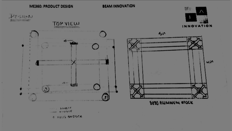
Modeling
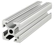
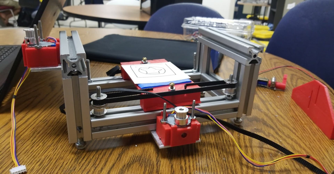
All of the aforementioned mechanisms would rest and operate on a frame made entirely from Aluminum 8020. A huge perk with using 8020 is that it features channels in which sliding mechanisms can easily interface with the stationary pieces. |
|
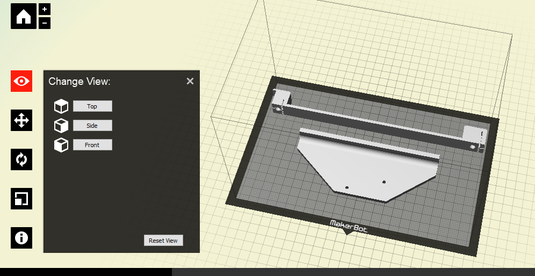
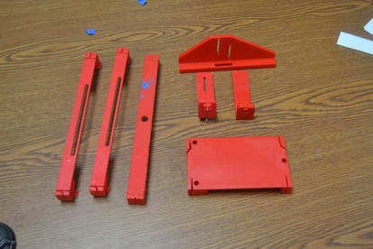
To make the mechanisms, we were provided with stepper motors, idler pulleys, set screw pulleys, and belts. Any other parts we needed were to be designed and manufactured on our own. This included that parts of the mechanism that interfaced with the belts such as the work-bed and the top bar which held the pen and solenoid assembly. A group member and I designed such parts on Solidworks and had them 3D printed. The final prototype had the following 3D printed parts:
- 2 Motor Blocks to hold the motors to the frame.
- A work-bed that could slide in the 8020 frame pieces to be controlled via the x-axis linear drive.
- A top bar that could slide into the 8020 frame pieces to be controlled via the y-axis linear drive. This bar would also hold the last few parts listed.
- A holder for the solenoid which could be adjusted to accommodate for different sized pens.
- A collar that would fit on the solenoid's plunger as well as the pen in order to interface the two together. This would allow the pen to move up and down with the solenoid's plunger.
In order to design these parts, certain measurements had to be taken. We standardized all of the tapped holes such that they would need 1/4-20 screws. This meant that all of the 3D printed holes would be the same. For the case with the motor blocks in particular, they were designed in order to house the motors, thus the motors had to be measured out. For the top bar and work-bed, the width and length of the frame had to be measured out as these parts spanned over these dimensions. The pen holder and collars were designed to be adjustable and adaptable. By adding slots and set screws to these parts and interfaces, any pen could be used with this device regardless of width and height (within reason).
As is the norm with prototyping via 3D printing, the parts we designed went through many iterations, many of which were a result of the parts not interfacing well with the rest of the assembly. Such issues that occurred during this process are as follows:
As is the norm with prototyping via 3D printing, the parts we designed went through many iterations, many of which were a result of the parts not interfacing well with the rest of the assembly. Such issues that occurred during this process are as follows:
- Many times, the parts were too complex for the 3D printer. This would cause the prints to fail, resulting in a tangled mess of stringy plastic.
- At times the support material of the 3D print would bind too much to the actual part and thus make it near impossible to separate.
- The printers themselves would fail. During one print, the extruder of the printer fell off of its guide rails. Another time the extruder would simply not extrude plastic. This was very frustrating.
- For the work-bed and the top bar, we printed sliders that would interface neatly with the 8020, allowing them to slide resistance free along the channels. However, sizing these sliders was a challenge because tolerance-ing had to be taken into consideration. If the dimensions were not correct, the sliders could jam and prevent any movement from occurring.
- For the same parts as mentioned in the last bullet point, the printed belt holders would also not interface neatly with the belts for the same reasons as with the sliders.
- Some parts were printed a tad too small due to the overlooked fact that the plastic parts would shrink ever so slightly as they cooled following a print.
- The entire pen-solenoid assembly was redesigned in order to hold the pen closer to the writing end rather then at the tip opposite of the writing end.
- Other parts such as the motor blocks were redesigned such that they interfaced with the frame better and more securely.
Assembly
Once all of the 3D parts were printed, it was time to assemble everything. For all interfaced parts, the screws were standardized to be 1/4-20. This Included all of the frame joints as well as the joints between the frame and the motor blocks. To properly make these joints, the 8020 was drilled and tapped in strategic locations in order to place the screws in a way that was out of sight, leaving the entire assembly with a very high aesthetic appeal.
Once all of the 3D parts were printed, it was time to assemble everything. For all interfaced parts, the screws were standardized to be 1/4-20. This Included all of the frame joints as well as the joints between the frame and the motor blocks. To properly make these joints, the 8020 was drilled and tapped in strategic locations in order to place the screws in a way that was out of sight, leaving the entire assembly with a very high aesthetic appeal.
|
The idler pulleys were all mounted onto the 8020 frame using 8-32 screws. The screw heads were slotted into the channels along with a washer. When in the correct position, a washer was placed on the screw such that the edges of the channel were sandwiched between the washers. Finally, a nut was tightened to secure the pulley screw in place. The pulleys were the simply placed on the screw. This was done for all 8 pulleys.
The pulleys themselves needed to be altered a bit. Because of the etch-a-sketch inspired design we decided to go with, half of the pulleys actually needed to be double pulleys that would rotate together. To accomplish this, two idler pulleys were places on top of each other and bound together using a mix of double-sided tape and hot glue. This design worked as it allows the two pulleys to spin as one which achieved the proposed mechanism design.
|
|
The work-bed and top bar were slid onto the assembly between the sets of pulleys. Once this was done, the entire frame could be assembled. This included attaching the motor-motor-block assemblies to the frame. An aside about the motor blocks, because they were only attached to the frame via one screw, a platform was placed underneath them that was attached to the frame as well that prevented any unwanted rotation. With the frame entirely assembled, the belts were placed onto the mechanisms. The belts were fastened to the top bar and work-bed, wrapped around all of the pulleys, and looped back to the top bar and work-bed where they slotted into the belt holders. This made for a secure loop that would not come undone.
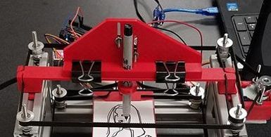
On top of the top bar rested the solenoid holder and pen-collar assembly. This assembly was simply clipped to the top bar in order to remain adjustable. The solenoid screwed in to the slots of the solenoid holder, allowing for its height to be adjusted. The collar was attached to its plunger which again was adjustable to accommodate for any size pen.
|
Throughout the assembly process, many different issues came up that had to be solved. Below are a list of these issues along with the solutions we came up with:
|
|
Circuit Design
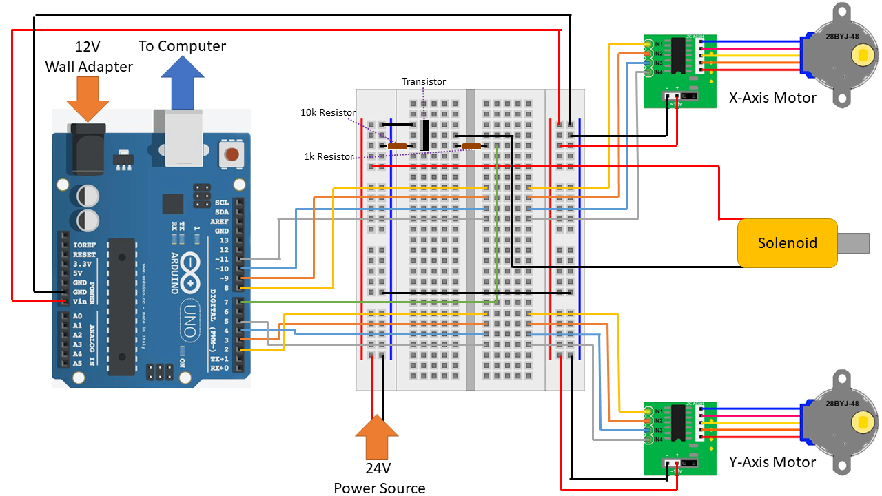
While I contributed to the mechanism, frame design, and 3D printed parts, the majority of my contributions were toward the electrical and control aspect of this project. I designed a circuit that allows the entire system to be controlled via an Arduino. To achieve this, I had to come up with three smaller circuits, each controlling a different axis. Two of these axes, the ones controlled by the stepper motors, had similar designs. Each motor had four signal pins and had to be connected to four digital pins on the Arduino. Additionally, the motors needed 12V to operate. To achieve this, I decided to power the Arduino via a 12V wall adapter which allowed me to connect the power pins from the motor directly to the Arduino's output and ground.
The last axis, the half axis, was the one that operated solenoid. This circuit was different because it could not be powered or controlled directly from the Arduino because the solenoid needed around 24V to operate where as an Arduino signal pin can only output 5V. Therefore, in order to control it I used a MOSFET transistor. The circuit was designed in such a way that the solenoid was powered via an external 24V source, in our case a power source. Within this current loop sat the transistor which was connected to one of the Arduino pins. This pin would open and close the transistor, allowing power to flow into the solenoid. When the transistor got a 5V signal, the solenoid would get power and plunge; this allows the pen to make contact with the paper and draw when it needed to.
Below is a diagram I made of my circuit:
The Code
The coding part of this project also fell under my domain. This part was inspired via an Arduino tutorial on how to make a CNC plotter, which can be found here.
The code has two main aspects to it: the Arduino Controller and the User Input.
Arduino Controller
The Arduino code that was offered by the website needed to be adjusted to fit the needs of this project. These adjustments were as follows:
On the user input side, a laptop can be used to send drawings to the Arduino for drawing. How this works is as follows:
The coding part of this project also fell under my domain. This part was inspired via an Arduino tutorial on how to make a CNC plotter, which can be found here.
The code has two main aspects to it: the Arduino Controller and the User Input.
Arduino Controller
The Arduino code that was offered by the website needed to be adjusted to fit the needs of this project. These adjustments were as follows:
- The code expects the pen to be controlled via a servo motor rather than a solenoid. I had to fix these parts of the code by removing the servo aspect and replacing it with a simple signal from the pin connected to the transistor.
- The pins that the motors were connected on the Arduino to had to be adjusted in order for the correct signals to go to the correct pins on the motor controller.
- The code needed to be calibrated. This meant making sure the values for the number of steps per revolution and steps per millimeter were correct for the specific motors we were using.
- I added a script that would zero the machine in the center of the workspace at start-up. This would ensure that all of the drawing would not go off of the page and also would test to make sure that the mechanisms were all working.
On the user input side, a laptop can be used to send drawings to the Arduino for drawing. How this works is as follows:
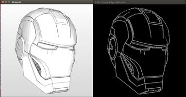
- The user creates a drawing using his or her favorite computer drawing program (i.e. Ms-Paint, Gimp, etc.).
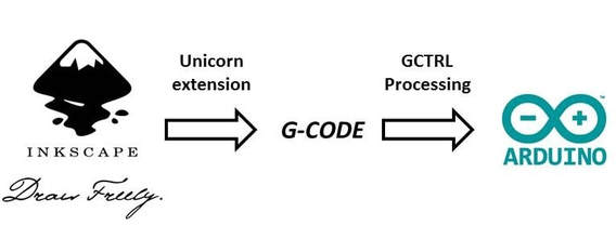
- The user then imports the image into Inkscape. This program will trace the image and convert the lines into paths. These paths will be saved as a .gcode file (note: GCode is the code that CNC machines read to complete tasks).
- On a separate window, a program called Processing 2 runs a JAVA program. This program creates the interface between the Arduino Board and the Computer.
- The user opens up the .gcode file in this Processing 2 program. The program proceeds to read the code line by line and sends it to the Arduino.
- The Arduino code interprets the lines as movements that the motors and solenoid need to make.
The end result is a physical drawing of what was made on the computer.
The Completed Prototype
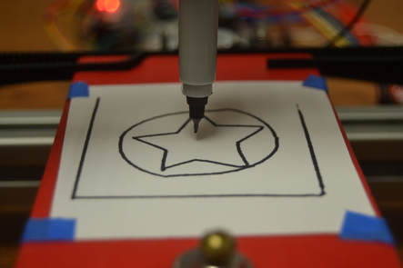
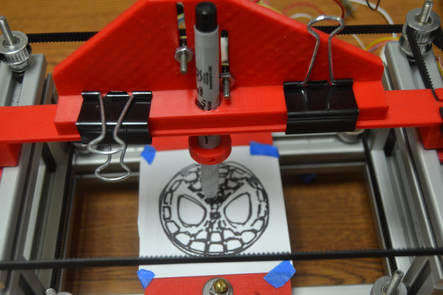
After about two months of hard work, we finally completed a working prototype. I personally was very happy with how it turned out. It still has its bugs, as to be expected with a prototype. The main issue is that the top bar that moves in the y-axis has a slight rock to it. This results in the pen having a very small delay while moving in this axis; this delay can be observed in the circle drawing. Despite this, all of the mechanisms work together very well, the circuity and coding is 100% functional, and all aspects of the project work together beautifully. We tested it out time after time again with various pictures including a simple shapes image I made on MS-Paint, the Spiderman logo, and even the Mona Lisa. Below are some images and videos of the final product:
After about two months of hard work, we finally completed a working prototype. I personally was very happy with how it turned out. It still has its bugs, as to be expected with a prototype. The main issue is that the top bar that moves in the y-axis has a slight rock to it. This results in the pen having a very small delay while moving in this axis; this delay can be observed in the circle drawing. Despite this, all of the mechanisms work together very well, the circuity and coding is 100% functional, and all aspects of the project work together beautifully. We tested it out time after time again with various pictures including a simple shapes image I made on MS-Paint, the Spiderman logo, and even the Mona Lisa. Below are some images and videos of the final product:
|
|
|
|
Bringing it to Market?
The final steps to this project were to plan on how bring this product to market. This included considering the following:
The final steps to this project were to plan on how bring this product to market. This included considering the following:
- Interviewing 3 to 5 possible customers in order to get feedback on the product.
- Creating a Bill of Materials, Manufacturing Guide, and Cost Estimation for 10,000 units
- Creating an Assembly Guide and User Manual
- Creating a Kickstarter-style video
This machine at the end of the day is a novelty, it is very cool and fun to play with but serves little purpose. Other plotters are available on the market that can be used for legitimate work. With this in mind, we thought, "why not make this in to a STEM education kit?". DIY kits are very successful ways to introduce STEM to kids in a way that is hands on and informative. DIY kits exist for 3D printers but we have not come across such a kit for a CNC Plotter. Our goal is that we would bring this to market as such a kit. This kit would be available to a wide range of people ages 13 and up and can be used to teach about very complicated concepts such a circuitry, mechanisms, and coding in a way that is easy to understand and fun. And at the end of the build, the "WOW!" factor would be that the student built a robot that can draw pictures.

User Manual
|
All information regarding Interviews/Feedback, Manufacturing Estimates, and the User Manual can be found in the User Manual. Click on the image to be taken to an online manual (I recommend using Chrome, Firefox or Edge to open this manual. Using Safari may result in formatting issues). |
