When I was a senior at Boston University, the College of Engineering was pushing toward a new model for the Senior Capstone Experience. Traditionally, the Fall semester of the Senior Design course was a class in Electro-mechanics and the Spring semester was all Senior Design project work. My year, they adopted a new model where half of the Fall semester would cover the material typically taught in Electro-mechanics and from there on would all be Senior Design work. Barring the chaos of being guinea pigs, part of this class's requirements was to work in a large team divided into sub teams in order to build a tile machine that could sort tiles, make a mosaic, and glue them together; all of this had to be done in 2-weeks. While it was strange to have a mini-project on top of the Senior Design project, the point of it was to prepare all of us for the Senior Design project by practicing all of the necessary skills we will need, both technical and organizational. I am proud to say that at the end of all of this, my group was the only group able to build a working machine at the end of the 2 allotted weeks.
|
Project Goals: Knowing how to work in interdisciplinary teams to achieve a common goal is a very useful skill, especially one that is utilized in the Senior Capstone experience as well as in industry. In addition, good organization and effective project management are necessary in order to meet deadlines, especially tight ones. The purpose of this project is to develop and exercise these skills while technical skill gained throughout college will be utilized to build a multi-function machine.
Learning Goals: Completion of this project utilized the following skills:
|
The Project
The overall goal of this project was to make a machine that accomplish the following tasks in succession:
Spoiler alert: We were only able to coordinate with the tile sorting group, the gluing group was not able to deliver a working sub-machine in time.
The overall goal of this project was to make a machine that accomplish the following tasks in succession:
- Take a handful of randomly selected tiles and sort them by color.
- Use the sorted tiles and place them on a 12x12 grid based on user input.
- Glue the mosaic together and remove it from the machine as a finished product.
Spoiler alert: We were only able to coordinate with the tile sorting group, the gluing group was not able to deliver a working sub-machine in time.
The Idea and Design
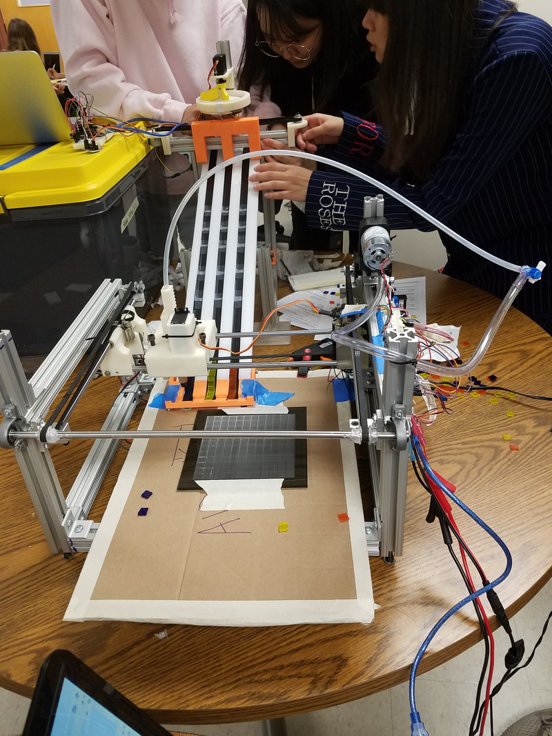
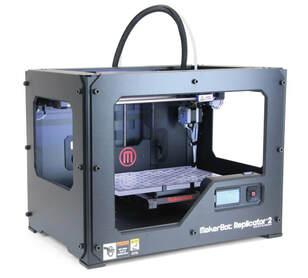
While my group has built a 2.5 axis machine in the past, it had a rather unorthodox design and a very small build area. This project on the other hand demanded a much larger build area and from experience, the design we used for the other project was difficult to go working. Therefore, we decided to base our design off of something we know works and works well, a 3D printer. In the workspace, there was an old, broken MakerBot Replicator 2 sitting off to the side. After getting permission from our Professor, we dissected the machine with the intent of reverse engineering it and studying how the mechanisms work. After a day of dissection and taking notes, we had a pretty good idea of how to build the x and y mechanism.
How the 3D printer works is as follows: there are three movement axes, x, y, and z. The x and y axis move the print nozzle to a specific location on the bed and the z axis moves the nozzle up and down. For our purposes, only the x and y axes are relevant. Both axis are actuated by a linear drive, but what is interesting is that the y axis is mounted onto the x axis. This means that as the x-axis moves, it moves the entire assembly that controls the y axis movement; this includes the motor, slider and the belt. We thought that this idea was easy to implement and the custom parts that we needed to make were simple.
For the z-axis, we decided to use a rack and pinion that could control the .5 axis motion. We figured that this was the easiest way to move the tile grabber up and down and because it was controlled via a servo, it was easy to be controlled and tuned. To pick up the tiles, we used a suction pump and a suction cup plunger. The plunger was affixed to the end of the z-axis such that the section cup would make contact with the smooth surface of the tile when it was plunged. The plunger had a tube running through it to a suction pump which would create a small vacuum in the suction cup so that we could pick up the tiles, move them to their locations, and place them.
All of the mechanisms would be controlled via an Arduino. We also wanted a user to be able to input whatever design they wanted, so we decided on creating a Python GUI that would interface with the Arduino. A user could graphically place the different colored tiles onto the grid on a computer, and the program would connect to the Arduino and send it the tile layout such that it would place the colored tiles in the correct spots on the print bed as the user defined.
Manufacturing the Prototype
Building the physical prototype was broken into three major sections:
The build for the frame was straight forward, it was all built from Aluminum 8020 bars that were drilled and tapped in order to be fastened together. L-brackets were used for some frame features that we thought were better to be adjustable in order to balance out things. Further, spaces were designated for the linear drive motors and the suction pump to be affixed to the frame. We made a grid by laser cutting a piece of acrylic (dubbed "the waffle") such that the tiles could sit securely in their spots on the bed once they were placed. This was also useful for writing the control algorithm because all the program needed to do was find the bottom right spot on the grid and the controller could accurately find all of the other spots since they were all precisely cut to be a set size and distance from each other. Finally, we fixed various components for the linear drives to the frame including the idle pulleys, the bars for the drive to slide on, and a balancing bar that would ensure that both sides of the x-axis would move at the same rate so there would be no twisting.
Building the physical prototype was broken into three major sections:
- The frame of the machine where everything would be mounted on.
- The liner drives for x and y movement.
- The mechanism for the z-axis actuation and tile pick up/put down.
The build for the frame was straight forward, it was all built from Aluminum 8020 bars that were drilled and tapped in order to be fastened together. L-brackets were used for some frame features that we thought were better to be adjustable in order to balance out things. Further, spaces were designated for the linear drive motors and the suction pump to be affixed to the frame. We made a grid by laser cutting a piece of acrylic (dubbed "the waffle") such that the tiles could sit securely in their spots on the bed once they were placed. This was also useful for writing the control algorithm because all the program needed to do was find the bottom right spot on the grid and the controller could accurately find all of the other spots since they were all precisely cut to be a set size and distance from each other. Finally, we fixed various components for the linear drives to the frame including the idle pulleys, the bars for the drive to slide on, and a balancing bar that would ensure that both sides of the x-axis would move at the same rate so there would be no twisting.
|
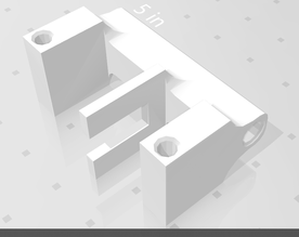
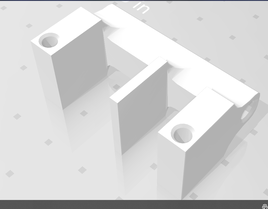
I was responsible for the linear drive mechanisms. Each linear drive consisted of a stepper motor and in idler pulley with a timing belt that wrapped them together, along with whatever carriage was to be carried along the drive. The x-axis was mounted directly onto the frame and the y-axis was mounted to the x-axis' linear drive. I designed two clips that would be able to house the y-axis' linear drive while also being able to interface with the x-axis' linear drive, allowing it to move along the sliding bars that were mounted onto the frame. One clip held the motor while the other clip held the idler pulley and was connected with two sliding bars that were press fitted into the clips. Each clip had a hole through them where a bushing could be press fitted such that the entire assembly could slide along the x-axis sliders with little friction on either side. Both of these clips were 3D printed as it was the easiest ways to prototype such a complex part in a short amount of time. And as they were parts that were subject to a heavy load, this method of manufacturing was suitable for the job.
The final piece of this puzzle was the design for the z half-axis. Because the half-axis was to be actuated via a servo, we decided to use a rack and pinion mechanism in order to ensure that the rotary motion was purely converted into controllable linear motion. Also, because the servo had a rotation limit, the was no way the mechanism would over-rotate and break. A carriage was designed that would be affixed to the y-axis and would hold the mechanism and plunger assembly. Again, these parts were 3D printed (including the rack and pinion), this time the reason was that 3D printing was the fastest way to attain the parts. This also worked out for our design because we were able to design the rack such that the tubing for the vacuum pump was able to be run through it, keeping things clean and out of the way. And this mechanism worked better than expected! With the structural part completed, it was time to wire and program the machine. |
|
The Circuit
I was in charge of designing circuitry for this project as I had the most experience with electronics. The power/control circuit had to accommodate the following components:
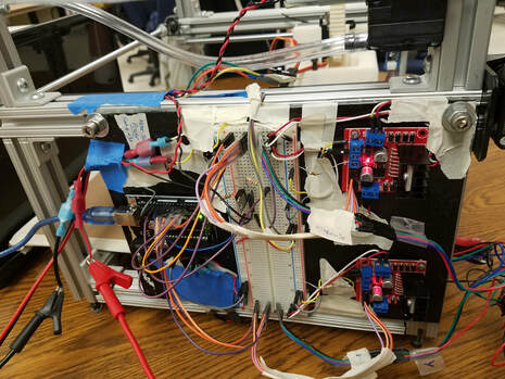
The suction pump was the last component to be connected to the circuit. Unlike all of the other components, the pump had to be connected to a secondary power supply. This is because it required much more power to run properly. As such, it would not be connected directly to the Arduino as it would surely fry the board. To turn the pump on and off, a MOSFET transistor was put in-line with the pump's power and connected to a digital pin. This would allow the pump to be turned on and off via a signal from the Arduino. Everything was firmly mounted to a board that was affixed to the frame. The nest of wires was also taped down so that things were out of the way and a bit more cleaner. The Arduino was not connected to any of the power sources. Because the circuit was a prototype, I though it better to have the Arduino to be powered from the computer via the USB connection to be safe.
One issue that I faced when building this circuit was that the circuit pulled a lot of current, close to 6 Amps. This was dangerous, when the machine would run with all of the motors active, the wires would start to burn and at one point they even melted. The best solution we decided on was to use a power supply that limited the current to 4 Amps. This solved the issue of having the wireds burn, but as a consequence the loads on the motors had to be reduced such that they could operate with a lesser torque. This involved using a lot of lubricant on the sliders, but we made it work.
I was in charge of designing circuitry for this project as I had the most experience with electronics. The power/control circuit had to accommodate the following components:
- 2 stepper motors
- 2 push button switches
- 1 servo motor
- 1 suction pump
- 1 Arduino
The suction pump was the last component to be connected to the circuit. Unlike all of the other components, the pump had to be connected to a secondary power supply. This is because it required much more power to run properly. As such, it would not be connected directly to the Arduino as it would surely fry the board. To turn the pump on and off, a MOSFET transistor was put in-line with the pump's power and connected to a digital pin. This would allow the pump to be turned on and off via a signal from the Arduino. Everything was firmly mounted to a board that was affixed to the frame. The nest of wires was also taped down so that things were out of the way and a bit more cleaner. The Arduino was not connected to any of the power sources. Because the circuit was a prototype, I though it better to have the Arduino to be powered from the computer via the USB connection to be safe.
One issue that I faced when building this circuit was that the circuit pulled a lot of current, close to 6 Amps. This was dangerous, when the machine would run with all of the motors active, the wires would start to burn and at one point they even melted. The best solution we decided on was to use a power supply that limited the current to 4 Amps. This solved the issue of having the wireds burn, but as a consequence the loads on the motors had to be reduced such that they could operate with a lesser torque. This involved using a lot of lubricant on the sliders, but we made it work.
Programming the Machine
The machine was all built and the circuitry was completed. All that remained was to program the micro-controller and the GUI, both of which I designed and wrote.
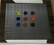
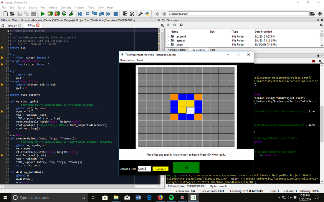
The GUI was written using Python. When the script was run, a window would come up that created a 12x12 grid that mirrored the physical one on the machine. A user could click on each grid square and cycle through the colors that each tile could be in order to place a tile. Three tile colors could be configured to be the three colors to be used int he design. The GUI also required that the user input the COM port where the Arduino was connected. Upon hitting connect on the GUI, the script would wake up and establish a connection to the Arduino. When hitting "GO", the script would instruct the Arduino to place each tile by color. When a tile was to be placed, the script would send the coordinates of the tile to the Arduino which would process the incoming information and move the machine to place the tile of the appropriate color. Throughout all of this, the Arduino sends messages back to Python script to ensure that the script does not move to the next tile without the previous tile having been placed. The messages are displayed in the GUI so that the user can monitor the progress of the process.
The machine was all built and the circuitry was completed. All that remained was to program the micro-controller and the GUI, both of which I designed and wrote.
The GUI was written using Python. When the script was run, a window would come up that created a 12x12 grid that mirrored the physical one on the machine. A user could click on each grid square and cycle through the colors that each tile could be in order to place a tile. Three tile colors could be configured to be the three colors to be used int he design. The GUI also required that the user input the COM port where the Arduino was connected. Upon hitting connect on the GUI, the script would wake up and establish a connection to the Arduino. When hitting "GO", the script would instruct the Arduino to place each tile by color. When a tile was to be placed, the script would send the coordinates of the tile to the Arduino which would process the incoming information and move the machine to place the tile of the appropriate color. Throughout all of this, the Arduino sends messages back to Python script to ensure that the script does not move to the next tile without the previous tile having been placed. The messages are displayed in the GUI so that the user can monitor the progress of the process.
The Arduino code used to control the machine was written such that it could interpret the coordinates being received by the Python GUI. First, the distance to the bottom right tile of the waffle, the distance between each tile of the waffle, and the homing positions for each tile color were hard coded into the script. Second, various functions were written in order to run the process.
- The first process would home the machine on start up. The motors would move the motors until both limit switches were hit.
- The second process would take the incoming tile coordinates, convert it to a distance from the homing position, and convert that distance into a number of steps for the stepper motors to take in the x and y directions.
- The next process would instruct the servo motor to plunge onto a tile, turn on the suction pump, and un-plunge. This would pick up a tile.
- The next process would move the tile to its place on the waffle based on the received coordinates.
- The next process would plunge the servo motor again, turn off the pump, and un-plunge. This would place the tile.
- The final process would return the motor to home by tracing the steps backwards, ready for the next coordinate to be received.
Tuning and Testing
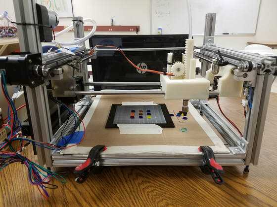
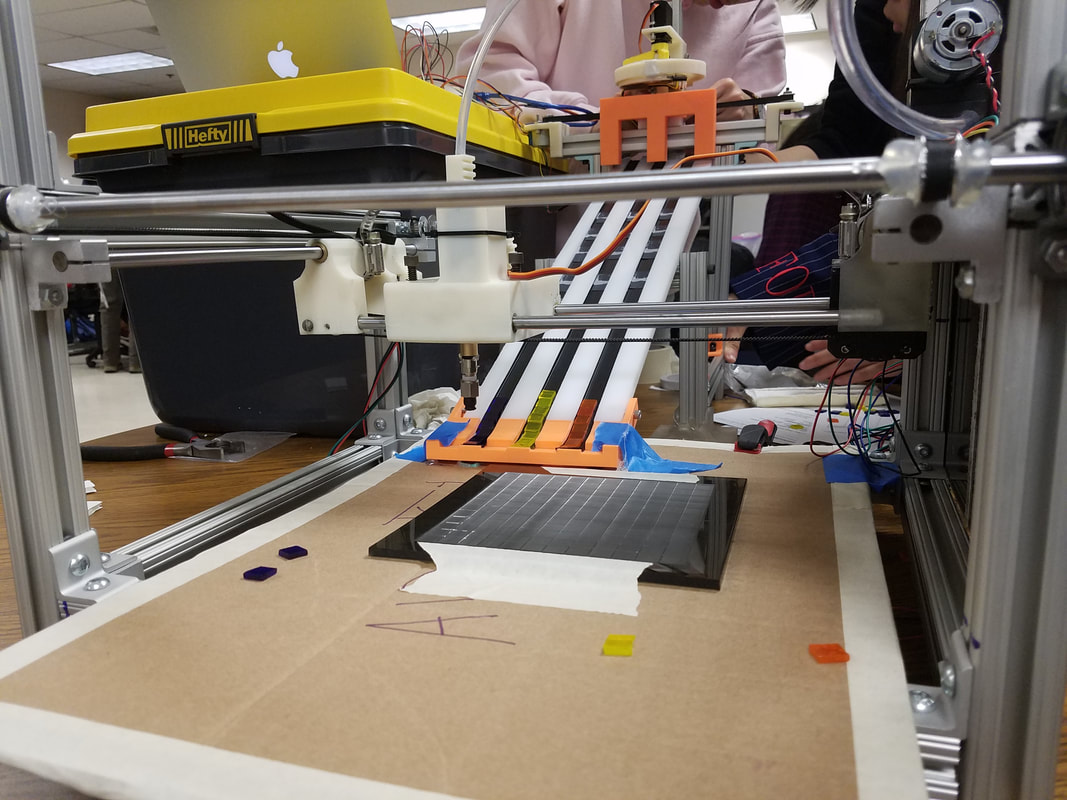
During testing of the code and the machine, we noticed a few things needed tuning. From the programming side of things, constants were adjusted so that the machine would move and place tiles in the correct places. Because this system was open loop, we had to play around with the constants until it was calibrated correctly. If time allotted, we would have used a closed loop system but at this point we were close to the deadline and the system we had already worked. The mechanisms needed some adjustments as well. For one, the sliders would get stuck at times, causing the timing belt to skip and ruining the process. To fix this, we cleaned and oiled the sliders and the bars and loosened the frame a bit to have the y axis sit a little loose on the x axis; this fixed the fixed the problem. Another issue we had was that the tile would not let go of the plunger when the pump was shut off, the vacuum would not evacuate fast enough. To fix this, we added a valve to the suction pump tube in order to have an adjustable controlled leak. This way, we could only have a partial vacuum in the suction cup such that the tile would stick when the pump was on but would drop when the pump turned off. To ensure the tile was released, I also programmed a delay where the plunger stayed down for a bit after the pump shut off, just to make sure the tile released every time. The last bit of the calibration was to optimize the movement in order to have the machine work as fast as possible without the process failing. This resulted in the following machine:
During testing of the code and the machine, we noticed a few things needed tuning. From the programming side of things, constants were adjusted so that the machine would move and place tiles in the correct places. Because this system was open loop, we had to play around with the constants until it was calibrated correctly. If time allotted, we would have used a closed loop system but at this point we were close to the deadline and the system we had already worked. The mechanisms needed some adjustments as well. For one, the sliders would get stuck at times, causing the timing belt to skip and ruining the process. To fix this, we cleaned and oiled the sliders and the bars and loosened the frame a bit to have the y axis sit a little loose on the x axis; this fixed the fixed the problem. Another issue we had was that the tile would not let go of the plunger when the pump was shut off, the vacuum would not evacuate fast enough. To fix this, we added a valve to the suction pump tube in order to have an adjustable controlled leak. This way, we could only have a partial vacuum in the suction cup such that the tile would stick when the pump was on but would drop when the pump turned off. To ensure the tile was released, I also programmed a delay where the plunger stayed down for a bit after the pump shut off, just to make sure the tile released every time. The last bit of the calibration was to optimize the movement in order to have the machine work as fast as possible without the process failing. This resulted in the following machine:
|
|
|
The Final Prototype and Coordinating
At this point we were all very proud of our work. In 2 weeks, we were able to build a fully functional tile placing machine that worked reliably and better than we expected. And from what the professors said, we were the only group that was able to build this section and went above and beyond by writing the Python GUI. Throughout the design, we had kept in mind that the other two sub teams had to interface with our machine. The tile sorting team was able to finish in time and we interfaced our two machines together. This did not affect how out machine operated, after a quick programming adjustment our machine was able to find the piles of sorted tiles that the previous group had processed. The team that was responsible for gluing the tiles together was not able to deliver on time, however. This is why our machine's base is made of cardboard, they were supposed to build the base to be fixed to our machine so that they can glue the final product at the end. Regardless, the tile sorting and placing sub machines interfaced nicely and worked like a charm.
At this point we were all very proud of our work. In 2 weeks, we were able to build a fully functional tile placing machine that worked reliably and better than we expected. And from what the professors said, we were the only group that was able to build this section and went above and beyond by writing the Python GUI. Throughout the design, we had kept in mind that the other two sub teams had to interface with our machine. The tile sorting team was able to finish in time and we interfaced our two machines together. This did not affect how out machine operated, after a quick programming adjustment our machine was able to find the piles of sorted tiles that the previous group had processed. The team that was responsible for gluing the tiles together was not able to deliver on time, however. This is why our machine's base is made of cardboard, they were supposed to build the base to be fixed to our machine so that they can glue the final product at the end. Regardless, the tile sorting and placing sub machines interfaced nicely and worked like a charm.
| Tile Machine software (Arduino and Python GUI) |
